Setup
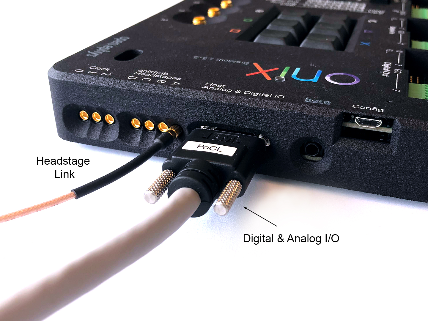
Connect the Breakout Board Digital and Analog I/O to the PCIe host board.
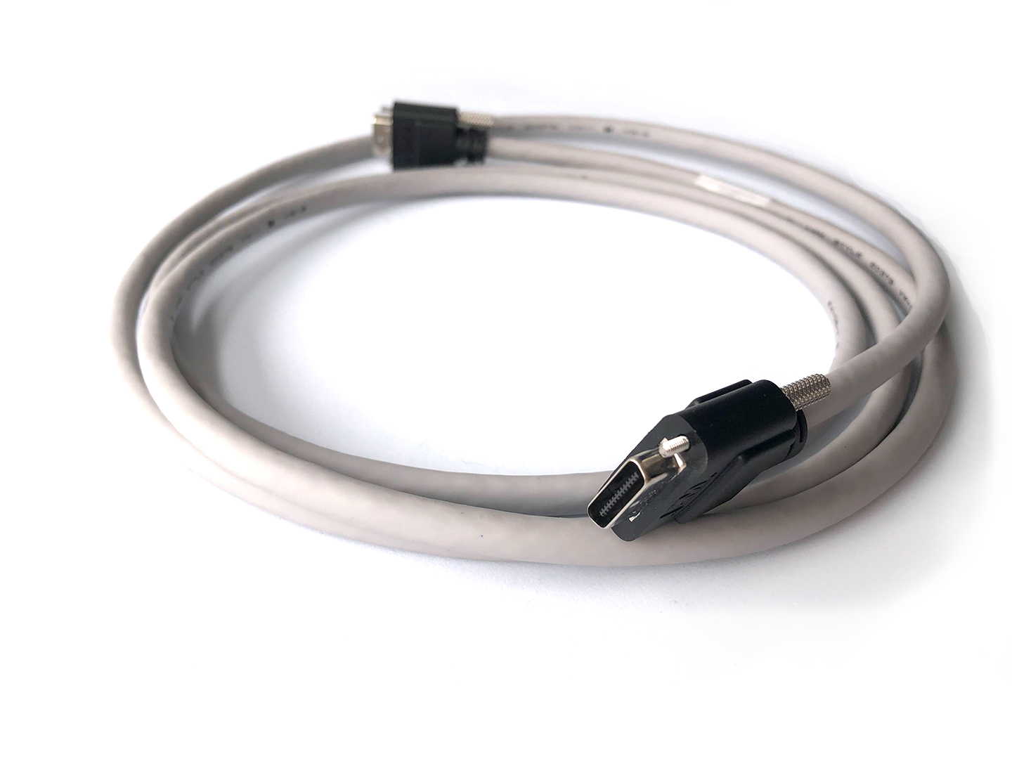
Use the SDR to SDR 26 POS cable to connect the Breakout Board to the PCIe host board. Though one end of this cable is marked with ‘camera’, the cable is symmetrical for our purposes, so it can be connected in either direction.
For each headstage or other measurement device, form a headstage line between the Breakout Board and the PCIe host board.
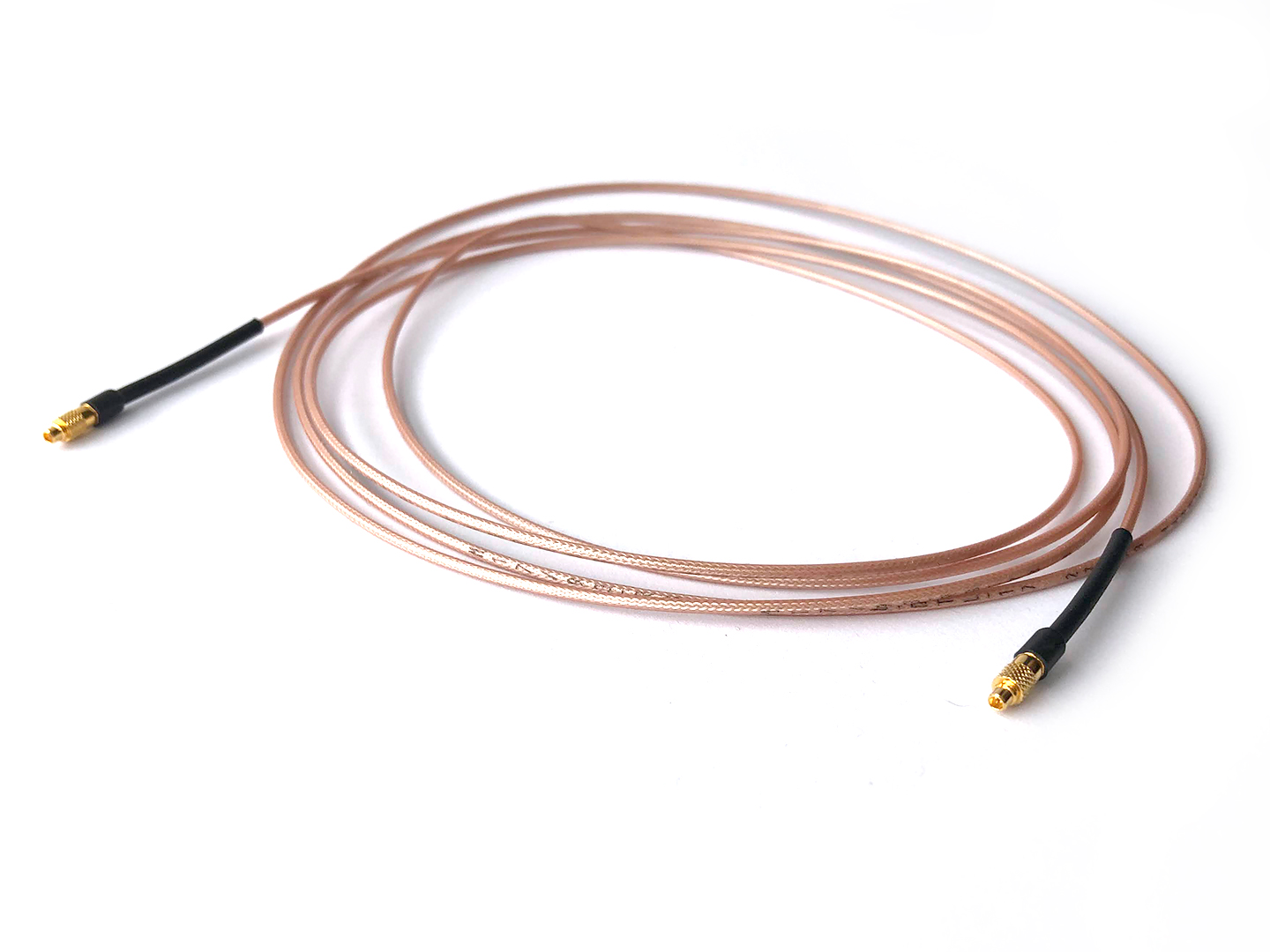
Use the MMCX to MMCX cable to connect the from PCIe host board to the breakout board. Use one line for each hub/headstage. Make sure that you are using the same port everywhere; i.e. port ‘A’ on the PCIe host board, the side of the Breakout Board, and the face of the Breakout Board.
The same cable type can be used to connect the clock in/output on the PCIe host board to the clock in/output on the breakout board.
Warning
See here how to connect and remove MMCX cables without damaging the connector.
If the lights on the Breakout Board are off, reset the Breakout Board by inserting a thin wire into the small hole just below the ‘Digital Out’ marking.
Attention
Some boards have a bug in the power on sequence that means a
reset is required before the board will work. This has been fixed in later revisions.
Operation
This board is behaves as if it was passive. It works in coordination with a host board. For every host, all IO is carried through the following connections:
Headstage link from PCIe host board (one line for each hub/headstage) (MMCX to MMCX cable). The same cable type can be used to connect the clock in/output on the PCIe host board to the clock in/output on the breakout board.
Digital and Analog I/O link from PCIe host board (SDR to SDR 26 POS cable)
Refer to the host documentation for a detailed description of how each of these signal lines are acquired.
Note
There may be more IO present on the breakout board than is available on a particular host board. For instance, PCIe Host has two coaxial links, but the breakout board provides four. This is is by design. The breakout is designed to be compatible with future host hardware.
Gateware
The breakout board contains a TinyFPGA BX (Lattice ICE40 breakout board) for digital input serialization, digital output deserialization, interpreting user input, and driving indication LEDs. The breakout board gateware is impelemented using an open-source toolchain (Yosys and NextPnR).
Updating the Gateware
If Open Ephys team have provided you with an updated firmware file for the Breakout Board, the micro-USB port on the Breakout Board (labelled ‘config’) can be used to update the firmware on the board.
Todo
Link and instructions