HS64 Optical Stimulator
- Authors
Jie (Jack) Zhang & Jonathan P. Newman
- IO
Register Access
- ONIX ID
5
- ONIX Hubs
Description
The HS64 Optical Stimulator is a two-channel high-current LED/laser diode driver for optogenetic stimulation (On Semi CAT4016). The maximal current can be set over a wide (~10 mA to 800 mA) range via an external digital potentiometer. The optical power can then be adjusted linearly and synchronously across both channels within this range over 8-levels per diode load. This sub-circuit is controlled as a single device using parameters similar to a Master8 or PulsePal.
Register Programming
Address |
Name |
Access |
Time of Effect |
POR Value |
Reset Action |
Description |
|---|---|---|---|---|---|---|
0x00 |
NULLPARM |
R |
N/A |
0 |
None |
No effect. |
0x01 |
MAXCURRENT |
R/W |
Immediate |
200 |
None |
Max LED/LD current, (0 to 255 = 800mA to 0 mA. See fig 10 of CAT4016 datasheet) |
0x02 |
PULSEMASK |
R/W |
Immediate |
(others => ‘1’) |
None |
Bitmask determining which of the (up to 32) channels is affected by trigger |
0x03 |
PULSEDUR |
R/W |
Immediate |
1000 |
None |
Pulse duration, microseconds |
0x04 |
PULSEPERIOD |
R/W |
Immediate |
50000 |
None |
Inter-pulse interval, microseconds |
0x05 |
BURSTCNT |
R/W |
Immediate |
5 |
None |
Burst duration, number of pulses in burst |
0x06 |
IBI |
R/W |
Immediate |
1000000 |
None |
Inter-burst interval, microseconds |
0x07 |
TRAINCNT |
R/W |
Immediate |
1 |
None |
Pulse train duration, number of bursts in train, 0 = continuous |
0x08 |
TRAINDELAY |
R/W |
Immediate |
0 |
None |
Pulse train delay, microseconds |
0x09 |
TRIGGER |
R/W |
Immediate |
0 |
Default |
Trigger stimulation (1 = deliver) |
0x0a |
ENABLE |
R/W |
Immediate |
0 |
Default |
1: enables the stimulator, 0: stimulator ignores triggers (so that a common trigger can be used) |
0x0b |
RESTMASK |
R/W |
Immediate |
(others => ‘0’) |
None |
Bitmask determining the “off” state of the up to 32 channels |
0x0c |
RESET |
R/W |
Immediate |
0 |
None |
If 1, Reset all parameters to default |
0x0d |
MINRHEOR |
R |
Immediate |
MINRHEOR |
Default |
The series resistor between the potentiometer (rheostat) and RSET bin on the CAT4016 |
0x0e |
POTRES |
R |
Immediate |
POTRES |
Default |
The resistance value of the potentiometer connected in rheostat config to RSET on CAT4016 |
A graphical register definitions are provided in the following diagrams:
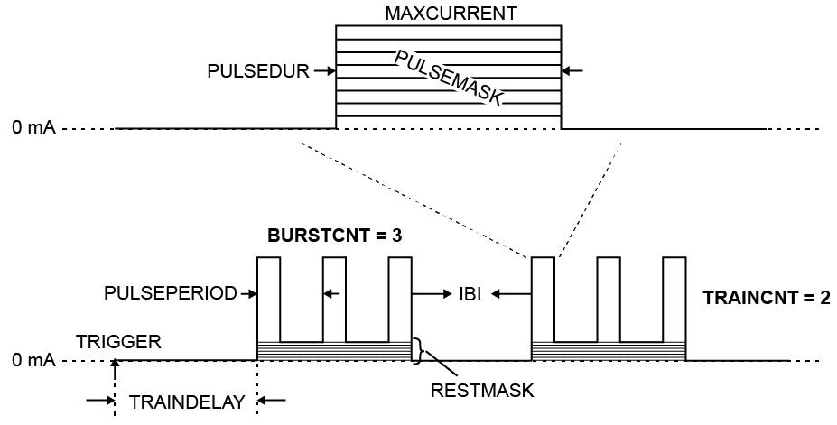
A diagram of the stimulus parameters presented in the HS64 Optical Stimulator Registers table.
Device To Host Data Frames
No frames are transmitted to the host.
Host To Device Data Frames
This device does not accept input frames. All write attempts will fail with an error.